Lab Video:
http://www.youtube.com/watch?v=Ic1zpIBN534&feature=youtu.be
———————————————————————————————————————————————————————
DV.h
/* a rtpkt is the packet sent from one routing update process to
another via the call tolayer3() */
struct rtpkt {
int sourceid; /* id of sending router sending this pkt */
int destid; /* id of router to which pkt being sent
(must be an immediate neighbor) */
int mincost[4]; /* min cost to node 0 … 3 */
};
struct distance_table
{
int costs[4][4];
};
void tolayer2(struct rtpkt packet);
// Node Prototypes
void rtinit0();
void rtinit1();
void rtinit2();
void rtinit3();
void rtupdate0(struct rtpkt *rcvdpkt);
void rtupdate1(struct rtpkt *rcvdpkt);
void rtupdate2(struct rtpkt *rcvdpkt);
void rtupdate3(struct rtpkt *rcvdpkt);
void linkhandler0(int linkid, int newcost);
void linkhandler1(int linkid, int newcost);
———————————————————————————————————————————————————————-
DV.CPP
// DV.cpp : Defines the entry point for the console application.
//
#include “stdafx.h”
#include <stdio.h>
#include <stdlib.h>
#include “DV.h”
#define LINKCHANGES 1
/* ******************************************************************
Programming assignment 3: implementing distributed, asynchronous,
distance vector routing.
THIS IS THE MAIN ROUTINE. IT SHOULD NOT BE TOUCHED AT ALL BY STUDENTS!
**********************************************************************/
int TRACE = 1; /* for my debugging */
int YES = 1;
int NO = 0;
void creatertpkt(struct rtpkt *initrtpkt,int srcid,int destid,int mincosts[])
{
int i;
initrtpkt->sourceid = srcid;
initrtpkt->destid = destid;
for (i=0; i<4; i++)
initrtpkt->mincost[i] = mincosts[i];
}
/*****************************************************************
***************** NETWORK EMULATION CODE STARTS BELOW ***********
The code below emulates the layer 2 and below network environment:
– emulates the tranmission and delivery (with no loss and no
corruption) between two physically connected nodes
– calls the initializations routines rtinit0, etc., once before
beginning emulation
THERE IS NOT REASON THAT ANY STUDENT SHOULD HAVE TO READ OR UNDERSTAND
THE CODE BELOW. YOU SHOLD NOT TOUCH, OR REFERENCE (in your code) ANY
OF THE DATA STRUCTURES BELOW. If you’re interested in how I designed
the emulator, you’re welcome to look at the code – but again, you should have
to, and you defeinitely should not have to modify
******************************************************************/
struct event {
float evtime; /* event time */
int evtype; /* event type code */
int eventity; /* entity where event occurs */
struct rtpkt *rtpktptr; /* ptr to packet (if any) assoc w/ this event */
struct event *prev;
struct event *next;
};
struct event *evlist = NULL; /* the event list */
/* possible events: */
#define FROM_LAYER2 2
#define LINK_CHANGE 10
float clocktime = 0.000;
void insertevent(struct event *p);
void init() /* initialize the simulator */
{
int i;
float sum, avg;
float jimsrand();
struct event *evptr;
printf(“Enter TRACE:”);
scanf_s(“%d”,&TRACE);
srand(9999); /* init random number generator */
sum = 0.0; /* test random number generator for students */
for (i=0; i<1000; i++)
sum=sum+jimsrand(); /* jimsrand() should be uniform in [0,1] */
avg = (float)(sum/1000.0);
if (avg < 0.25 || avg > 0.75) {
printf(“It is likely that random number generation on your machine\n” );
printf(“is different from what this emulator expects. Please take\n”);
printf(“a look at the routine jimsrand() in the emulator code. Sorry. \n”);
exit(0);
}
clocktime=0.0; /* initialize time to 0.0 */
rtinit0();
rtinit1();
rtinit2();
rtinit3();
/* initialize future link changes */
if (LINKCHANGES==1) {
evptr = (struct event *)malloc(sizeof(struct event));
evptr->evtime = 10000.0;
evptr->evtype = LINK_CHANGE;
evptr->eventity = -1;
evptr->rtpktptr = NULL;
insertevent(evptr);
evptr = (struct event *)malloc(sizeof(struct event));
evptr->evtype = LINK_CHANGE;
evptr->evtime = 20000.0;
evptr->rtpktptr = NULL;
insertevent(evptr);
}
}
/****************************************************************************/
/* jimsrand(): return a float in range [0,1]. The routine below is used to */
/* isolate all random number generation in one location. We assume that the*/
/* system-supplied rand() function return an int in therange [0,mmm] */
/****************************************************************************/
float jimsrand()
{
double mmm = RAND_MAX; /* largest int – MACHINE DEPENDENT!!!!!!!! */
float x; /* individual students may need to change mmm */
x = (float)(rand()/mmm); /* x should be uniform in [0,1] */
return(x);
}
/********************* EVENT HANDLINE ROUTINES *******/
/* The next set of routines handle the event list */
/*****************************************************/
void insertevent(struct event *p)
{
struct event *q,*qold;
if (TRACE>3) {
printf(” INSERTEVENT: time is %lf\n”,clocktime);
printf(” INSERTEVENT: future time will be %lf\n”,p->evtime);
}
q = evlist; /* q points to header of list in which p struct inserted */
if (q==NULL) { /* list is empty */
evlist=p;
p->next=NULL;
p->prev=NULL;
}
else {
for (qold = q; q !=NULL && p->evtime > q->evtime; q=q->next)
qold=q;
if (q==NULL) { /* end of list */
qold->next = p;
p->prev = qold;
p->next = NULL;
}
else if (q==evlist) { /* front of list */
p->next=evlist;
p->prev=NULL;
p->next->prev=p;
evlist = p;
}
else { /* middle of list */
p->next=q;
p->prev=q->prev;
q->prev->next=p;
q->prev=p;
}
}
}
void printevlist()
{
struct event *q;
printf(“————–\nEvent List Follows:\n”);
for(q = evlist; q!=NULL; q=q->next) {
printf(“Event time: %f, type: %d entity: %d\n”,q->evtime,q->evtype,q->eventity);
}
printf(“————–\n”);
}
/************************** TOLAYER2 ***************/
void tolayer2(struct rtpkt packet)
{
struct rtpkt *mypktptr;
struct event *evptr, *q;
float jimsrand(),lastime;
int i;
int connectcosts[4][4];
/* initialize by hand since not all compilers allow array initilization */
connectcosts[0][0]=0; connectcosts[0][1]=1; connectcosts[0][2]=3;
connectcosts[0][3]=7;
connectcosts[1][0]=1; connectcosts[1][1]=0; connectcosts[1][2]=1;
connectcosts[1][3]=999;
connectcosts[2][0]=3; connectcosts[2][1]=1; connectcosts[2][2]=0;
connectcosts[2][3]=2;
connectcosts[3][0]=7; connectcosts[3][1]=999; connectcosts[3][2]=2;
connectcosts[3][3]=0;
/* be nice: check if source and destination id’s are reasonable */
if (packet.sourceid<0 || packet.sourceid >3) {
printf(“WARNING: illegal source id in your packet, ignoring packet!\n”);
return;
}
if (packet.destid<0 || packet.destid >3) {
printf(“WARNING: illegal dest id in your packet, ignoring packet!\n”);
return;
}
if (packet.sourceid == packet.destid) {
printf(“WARNING: source and destination id’s the same, ignoring packet!\n”);
return;
}
if (connectcosts[packet.sourceid][packet.destid] == 999) {
printf(“WARNING: source and destination not connected, ignoring packet!\n”);
return;
}
/* make a copy of the packet student just gave me since he/she may decide */
/* to do something with the packet after we return back to him/her */
mypktptr = (struct rtpkt *) malloc(sizeof(struct rtpkt));
mypktptr->sourceid = packet.sourceid;
mypktptr->destid = packet.destid;
for (i=0; i<4; i++)
mypktptr->mincost[i] = packet.mincost[i];
if (TRACE>2) {
printf(” TOLAYER2: source: %d, dest: %d\n costs:”,
mypktptr->sourceid, mypktptr->destid);
for (i=0; i<4; i++)
printf(“%d “,mypktptr->mincost[i]);
printf(“\n”);
}
/* create future event for arrival of packet at the other side */
evptr = (struct event *)malloc(sizeof(struct event));
evptr->evtype = FROM_LAYER2; /* packet will pop out from layer3 */
evptr->eventity = packet.destid; /* event occurs at other entity */
evptr->rtpktptr = mypktptr; /* save ptr to my copy of packet */
/* finally, compute the arrival time of packet at the other end.
medium can not reorder, so make sure packet arrives between 1 and 10
time units after the latest arrival time of packets
currently in the medium on their way to the destination */
lastime = clocktime;
for (q=evlist; q!=NULL ; q = q->next)
if ( (q->evtype==FROM_LAYER2 && q->eventity==evptr->eventity) )
lastime = q->evtime;
evptr->evtime = (float)(lastime + 2.*jimsrand());
if (TRACE>2)
printf(” TOLAYER2: scheduling arrival on other side\n”);
insertevent(evptr);
}
int _tmain(int argc, _TCHAR* argv[])
{
struct event *eventptr;
init();
while (1) {
eventptr = evlist; /* get next event to simulate */
if (eventptr==NULL)
goto terminate;
evlist = evlist->next; /* remove this event from event list */
if (evlist!=NULL)
evlist->prev=NULL;
if (TRACE>1) {
printf(“MAIN: rcv event, t=%.3f, at %d”,
eventptr->evtime,eventptr->eventity);
if (eventptr->evtype == FROM_LAYER2 ) {
printf(” src:%2d,”,eventptr->rtpktptr->sourceid);
printf(” dest:%2d,”,eventptr->rtpktptr->destid);
printf(” contents: %3d %3d %3d %3d\n”,
eventptr->rtpktptr->mincost[0], eventptr->rtpktptr->mincost[1],
eventptr->rtpktptr->mincost[2], eventptr->rtpktptr->mincost[3]);
}
}
clocktime = eventptr->evtime; /* update time to next event time */
if (eventptr->evtype == FROM_LAYER2 ) {
if (eventptr->eventity == 0)
rtupdate0(eventptr->rtpktptr);
else if (eventptr->eventity == 1)
rtupdate1(eventptr->rtpktptr);
else if (eventptr->eventity == 2)
rtupdate2(eventptr->rtpktptr);
else if (eventptr->eventity == 3)
rtupdate3(eventptr->rtpktptr);
else { printf(“Panic: unknown event entity\n”); exit(0); }
}
else if (eventptr->evtype == LINK_CHANGE ) {
if (clocktime<10001.0) {
linkhandler0(1,20);
linkhandler1(0,20);
}
else {
linkhandler0(1,1);
linkhandler1(0,1);
}
}
else
{ printf(“Panic: unknown event type\n”); exit(0); }
if (eventptr->evtype == FROM_LAYER2 )
free(eventptr->rtpktptr); /* free memory for packet, if any */
free(eventptr); /* free memory for event struct */
}
terminate:
printf(“\nSimulator terminated at t=%f, no packets in medium\n”, clocktime);
}
———————————————————————————————————————————————————————-
The Nodes are very Similar, see video above for differences, posted below is only node 0
#include “stdafx.h”
#include “DV.h”
extern int TRACE;
extern int YES;
extern int NO;
int connectcosts0[4] = { 0, 1, 3, 7};//costs to other nodes
static distance_table dt;
/* students to write the following two routines, and maybe some others */
void rtinit0()
{
struct rtpkt rtpacket;
// for all destinations y in N:
for(int j=0;j<4;j++)
for(int k=0;k<4;k++) dt.costs[j][k] = 999;
dt.costs[0][0] = connectcosts0[0];
dt.costs[0][1] = connectcosts0[1];
dt.costs[0][2] = connectcosts0[2];
dt.costs[0][3] = connectcosts0[3];
// for each neighbor source is “me” must change in other files.
rtpacket.sourceid = 0;
rtpacket.mincost[0] = dt.costs[rtpacket.sourceid][0];
rtpacket.mincost[1] = dt.costs[rtpacket.sourceid][1];
rtpacket.mincost[2] = dt.costs[rtpacket.sourceid][2];
rtpacket.mincost[3] = dt.costs[rtpacket.sourceid][3];
for(int i = 0;i<4;i++)
if ((i!=rtpacket.sourceid)&&(dt.costs[rtpacket.sourceid][i]!=999))
{
rtpacket.destid = i;
tolayer2(rtpacket);
}
}
void rtupdate0(struct rtpkt *rcvdpkt)
{
struct rtpkt rtpacket;
// the node sending me information is “from” or v in the text on page 373
int v = rcvdpkt->sourceid;
// x is “me” the node that i am at. must change in other files.
int x = 0;
//
bool DV_Changed = false;
// update the location in my cost table
dt.costs[v][0] = rcvdpkt->mincost[0];
dt.costs[v][1] = rcvdpkt->mincost[1];
dt.costs[v][2] = rcvdpkt->mincost[2];
dt.costs[v][3] = rcvdpkt->mincost[3];
// The node that sent me information is v;
// page 373
// dt.costs os c on page 373 in the text
int c_v_x = dt.costs[x][v]; // this is part of line 14
for (int y = 0;y<4;y++)
{
if (y != x)
{
int D_x_y = dt.costs[x][y];
int D_v_y = dt.costs[v][y];
int new_D_x_y = c_v_x + D_v_y;
if (new_D_x_y < D_x_y)
{
dt.costs[x][y] = new_D_x_y;
DV_Changed = true;
}
}
}
if (DV_Changed)
{
// tell my neighbors
rtpacket.sourceid = x;
rtpacket.mincost[0] = dt.costs[rtpacket.sourceid][0];
rtpacket.mincost[1] = dt.costs[rtpacket.sourceid][1];
rtpacket.mincost[2] = dt.costs[rtpacket.sourceid][2];
rtpacket.mincost[3] = dt.costs[rtpacket.sourceid][3];
for(int i = 0;i<4;i++)
if ((i!=rtpacket.sourceid)&&(dt.costs[rtpacket.sourceid][i]!=999))
{
rtpacket.destid = i;
tolayer2(rtpacket);
}
}
}
void printdt0(struct distance_table *dtptr)
{
printf(” via \n”);
printf(” D0 | 1 2 3 \n”);
printf(” —-|—————–\n”);
printf(” 1| %3d %3d %3d\n”,dtptr->costs[1][1],
dtptr->costs[1][2],dtptr->costs[1][3]);
printf(“dest 2| %3d %3d %3d\n”,dtptr->costs[2][1],
dtptr->costs[2][2],dtptr->costs[2][3]);
printf(” 3| %3d %3d %3d\n”,dtptr->costs[3][1],
dtptr->costs[3][2],dtptr->costs[3][3]);
}
void linkhandler0(int linkid, int newcost)
/* called when cost from 0 to linkid changes from current value to newcost*/
/* You can leave this routine empty if you’re an undergrad. If you want */
/* to use this routine, you’ll need to change the value of the LINKCHANGE */
/* constant definition in prog3.c from 0 to 1 */
{
}
Problem #4: Consider the network below:
a.Suppose that this network is a datagram network. Show the forwarding table in router A, such that all traffic destined to host H3 is forwarded through interface 3.
|
Header Value Destination |
Output Interface Link |
| H3 |
3 |
b.Suppose that this network is a datagram network. Can you write down a forwarding table in router A, such that all traffic from H1 destined to host H3 is forwarded through interface 3, while all traffic from H2 destined to host H3 is forwarded through interface 4? (Hint: this is a trick question.)
- No, this is impossible. A datagram bases what path to take based off of the destination. If the output link from router A is determined to be link 3 as denoted in the routing table above, then this will be the only path that H2 will be able to send on. H2 can only tell the datagram to send to router A, from there router A will pick the link with the lowest cost, which is link 3.
c. Now suppose that this network is a virtual circuit network and that there is one ongoing call between H1 and H3, and another ongoing call between H2 and H3. Write down a forwarding table in router A, such that all traffic from H1 destined to host H3 is forwarded through interface 3, while all traffic from H2 destined to host H3 is forwarded through interface 4.
|
Host |
Virtual Circuit Number |
Outgoing Link |
Outgoing Circuit Number |
|
H1 |
20 | 3 | 52 |
|
H2 |
531 | 4 |
981 |
d.Assuming the same scenario as (c), write down the forwarding tables in nodes B, C, and D
|
VC Router (through B) |
Incoming VC Number |
Link |
Outgoing VC Number |
|
A |
20 |
3 |
52 |
|
B |
52 |
2 |
98 |
|
D |
98 |
3 |
7 |
|
VC Router (through C) |
Incoming VC Number |
Link |
Outgoing VC Number |
|
A |
531 |
4 |
981 |
|
C |
981 |
2 |
56 |
|
D |
56 |
3 |
12 |
Problem #6: In the text we have used the term connection-oriented service to describe a transport-layer service and connection service for a network-layer service.Why the subtle shades in terminology?
- The reason for the subtle change in terminology is due to the ways that the network interacts along the path. The transport layer connection oriented service is implemented at the edge of the network in the end systems, where the network layers connection service is implemented at both the end systems and the routers along the path (Kurose, Ch4.2, 4/12/13). The Network layers connection service, known as a virtual circuit, mandates that the routers along the path must maintain state with each other and know of the next router in the path towards the destination until the connection has been terminated by one of the end systems. In a connection-oriented service , over the transport layer, or TCP, a handshake is made, and correct inorder delivery is promised, however, unlike in a virtual circuit where all traffic takes the same path, the datagrams in TCP can take a different path and show up out of order before being reorganized. TCP simulates a connection, where a virtual circuit is a constant connection maintained through the communicating hosts.
Problem #10: Consider a datagram network using 32-bit host addresses. Suppose a router has four links, numbered 0 through 3, and packets are to be forwarded to the link interfaces as follows:
Destination Address Range Link Interface
| Address | Link |
| 11100000 00 (/10) | 0 |
| 11100000 01(/10) | 1 |
| 11100000 01000001 (/16) | 2 |
| 11100001(/8) | 2 |
| Otherwise | 3 |
- Interface 3
- Interface 1
11100001 10000000 00010001 01110111
- Interface 2
| Prefix | Min | Max | Range |
| 00 | 00000000= 0 | 00111111 = 63 | 64 |
| 010 | 01000000 = 64 | 01011111 = 95 | 32 |
| 011 | 01100000= 96 | 01111111 = 127 | 32 |
| 10 | 10000000 = 128 | 10111111 = 191 | 64 |
| 11 | 11000000 = 192 | 11111111 = 255 | 64 |
- The minimum number of the address and the maximum number of the address can be found by substituting 0 (min) or 1(max) for the remaining bits in an 8 bit address not defined by the prefix. The Range can then be found as the difference between the minimum possible value and the maximum possible value
- According to Dijkstra’s Algorithm, the routers figure out to which host they can make the fastest hop based on the cost. For example, in my first table shown below, the routing table for T, the first hop made is to U as the cost is the smallest at 3. After U has joined the new supernode TU, you add the cost (2) of getting from T to U to the links not contained within the supernode because in the case that the packet reaches the next node, in T’s case V through U it must take the time fro m T->U and U->V, in this case, it does not pass through T to reach V, but that is the general concept,
- T Routing Table
![IMG_0552[1]](https://maxwellsullivan.files.wordpress.com/2013/04/img_05521.jpg)
-
U Routing Table
![IMG_0558[1]](https://maxwellsullivan.files.wordpress.com/2013/04/img_05581.jpg)
- W Routing Table
![IMG_0550[1]](https://maxwellsullivan.files.wordpress.com/2013/04/img_05501.jpg)
- V Routing Table
![IMG_0551[1]](https://maxwellsullivan.files.wordpress.com/2013/04/img_05511.jpg)
- Y Routing Table
![IMG_0560[1]](https://maxwellsullivan.files.wordpress.com/2013/04/img_05601.jpg)
- Z Routing Table
![IMG_0559[1]](https://maxwellsullivan.files.wordpress.com/2013/04/img_05591.jpg)
![IMG_0556[1]](https://maxwellsullivan.files.wordpress.com/2013/04/img_05561.jpg)
- eBGP, because router 3c would learn about x from router 4c, which means that it would hear from another AS .
- OSPF 3a would learn about x from 3b, which means that it is learning about x from 3b, which because it is not on any border is only able to run OSPF.
c.Router 1c learns about x from which routing protocol?
- eBGP, learns about X from 3a, which means that it is learning from another AS
- RIP, learns about X from 1a, which is not on any borders and therefore is only running RIP to communicate with other hosts on its network.
![IMG_0557[1]](https://maxwellsullivan.files.wordpress.com/2013/04/img_05571.jpg)
- The image above shows 32 receivers(the darkened nodes at the bottom) connected to a single sender through a binary tree configuration in which each node can have a maximum of 2 connections. According to the network layer broadcast, a packet is sent over each link only once. Therefore, the number of link crossings can be determined by the number of edges that connect each node or 2+4+8+16+32 or 62 total link crossings. With unicast emulation, the sender sends a copy of the packet to each of the 32 receivers. Each packet must traverse 5 hops before reaching the 32 receivers, which means that the total number of link crossings can be denoted as 5*32 for the number of hops*the number of end packets or 160 total crossings.
Lab Video:
http://www.youtube.com/watch?v=P7ulCo2PnDU&feature=youtu.be
———————————————————————————————————————————————————————-
Steps:
1. Begin by opening the Windows Command Prompt application. As shown in Figure 1, enter “ipconfig /release”.
2. Start up the Wireshark packet sniffer, as described in the introductory Wireshark lab and begin Wireshark packet capture.
3. Now go back to the Windows Command Prompt and enter “ipconfig /renew”. This instructs your host to obtain a network configuration, including a new IP address. In Figure 1, the host obtains the IP address 192.168.1.108
4. Wait until the “ipconfig /renew” has terminated. Then enter the same command “ipconfig /renew” again.
5. When the second “ipconfig /renew” terminates, enter the command “ipconfig/release” to release the previously-allocated IP address to your computer.
6. Finally, enter “ipconfig /renew” to again be allocated an IP address for your computer.
7. Stop Wireshark packet capture.
———————————————————————————————————————————————————————-
Questions:
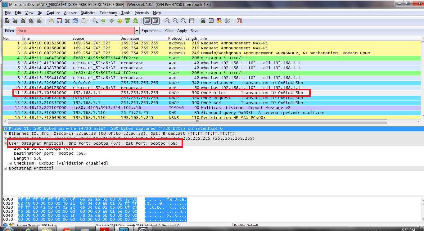
1. Are DHCP messages sent over UDP or TCP?
- The DHCP messages are sent via UDP.
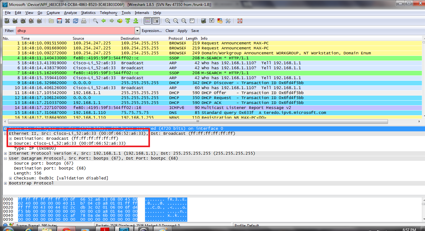
3. What is the link-layer (e.g., Ethernet) address of your host?
- The ethernet address of my host is 00:0f:66:52:a6:33
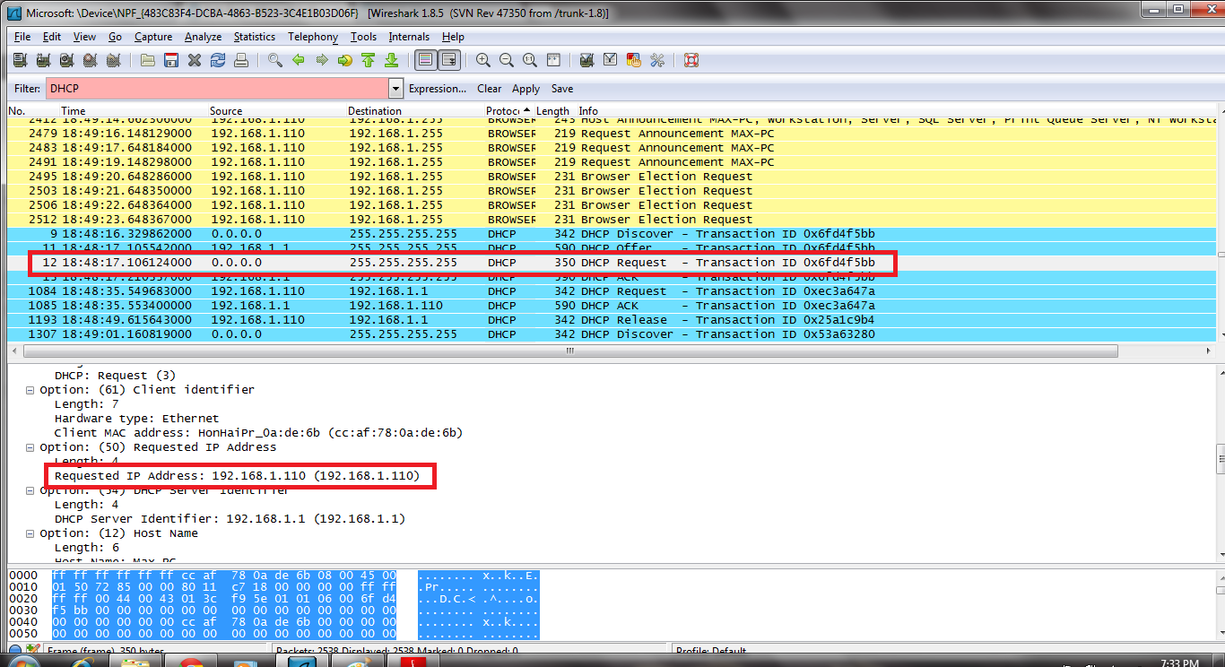
4. What values in the DHCP discover message differentiate this message from the DHCP request message?
- DHCP Message Type
- Request includes a server identifier field
5. What is the value of the Transaction-ID in each of the first four (Discover/Offer/Request/ACK) DHCP messages? What are the values of the Transaction-ID in the second set (Request/ACK) set of DHCP messages? What is the purpose of the Transaction-ID field?
- 1st set of messages: 0x6fd4f5bb
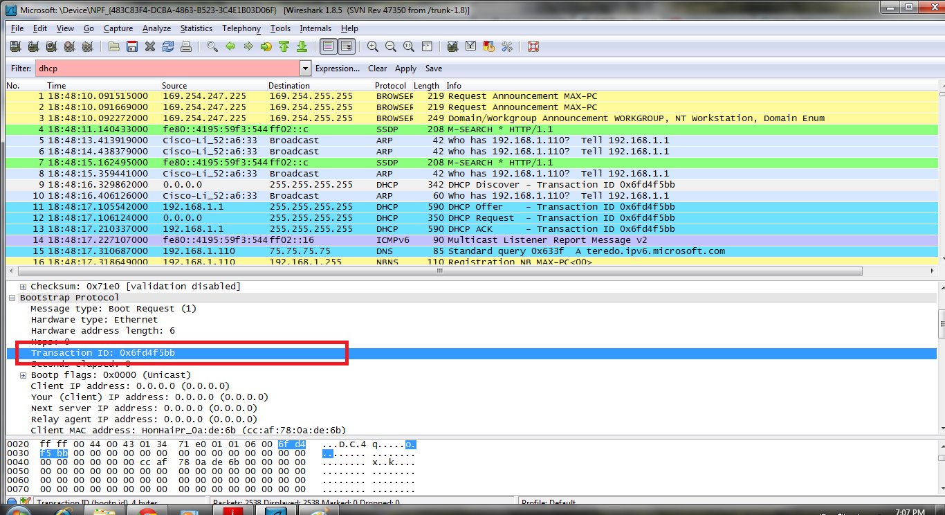
- 2nd Set of messages: 0x53a63280

- Purpose: The transaction ID is different so that the host can differentiate between different requests made by the user.
6. A host uses DHCP to obtain an IP address, among other things. But a host’s IP address is not confirmed until the end of the four-message exchange! If the IP address is not set until the end of the four-message exchange, then what values are used in the IP datagrams in the four-message exchange? For each of the four DHCP messages (Discover/Offer/Request/ACK DHCP), indicate the source and destination IP addresses that are carried in the encapsulating IP datagram.
- Discover: 0.0.0.0/255.255.255.255
- Offer: 192.168.1.1/255.255.255.255
- Request: 0.0.0.0/255.255.255.255
- ACK:192.168.1.1/255.255.255.255
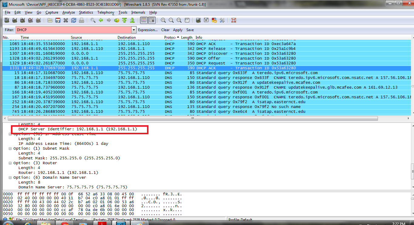
7. What is the IP address of your DHCP server?
- 192.168.1.1
8. What IP address is the DHCP server offering to your host in the DHCP Offer message? Indicate which DHCP message contains the offered DHCP address.
- My client is offered 192.168.1.10 by the DHCP server. The offer message contains the DHCP address offered by the server

9. In the example screenshot in this assignment, there is no relay agent between the host and the DHCP server. What values in the trace indicate the absence of a relay agent? Is there a relay agent in your experiment? If so what is the IP address of the agent?
- In the example given, the value that indicates there is no relay agent is 0.0.0.0, in the case of my capture, I also have a value for the relay agent of 0.0.0.0 indicating that I too did not have a relay agent.
10. Explain the purpose of the router and subnet mask lines in the DHCP offer message.
- The subnet mask line tells the client which subnet mask to use.
- The router line indicates where the client should send messages by default.
11. In the DHCP trace file noted in footnote 2, the DHCP server offers a specific IP address to the client (see also question 8. above). In the client’s response to the first server OFFER message, does the client accept this IP address? Where in the client’s RESPONSE is the client’s requested address?
- The client accepts the IP address given in the offer message within the request message. After being offered the IP address 192.168.1.110 in the offer message, my client sent back a message further requesting that specific IP address.
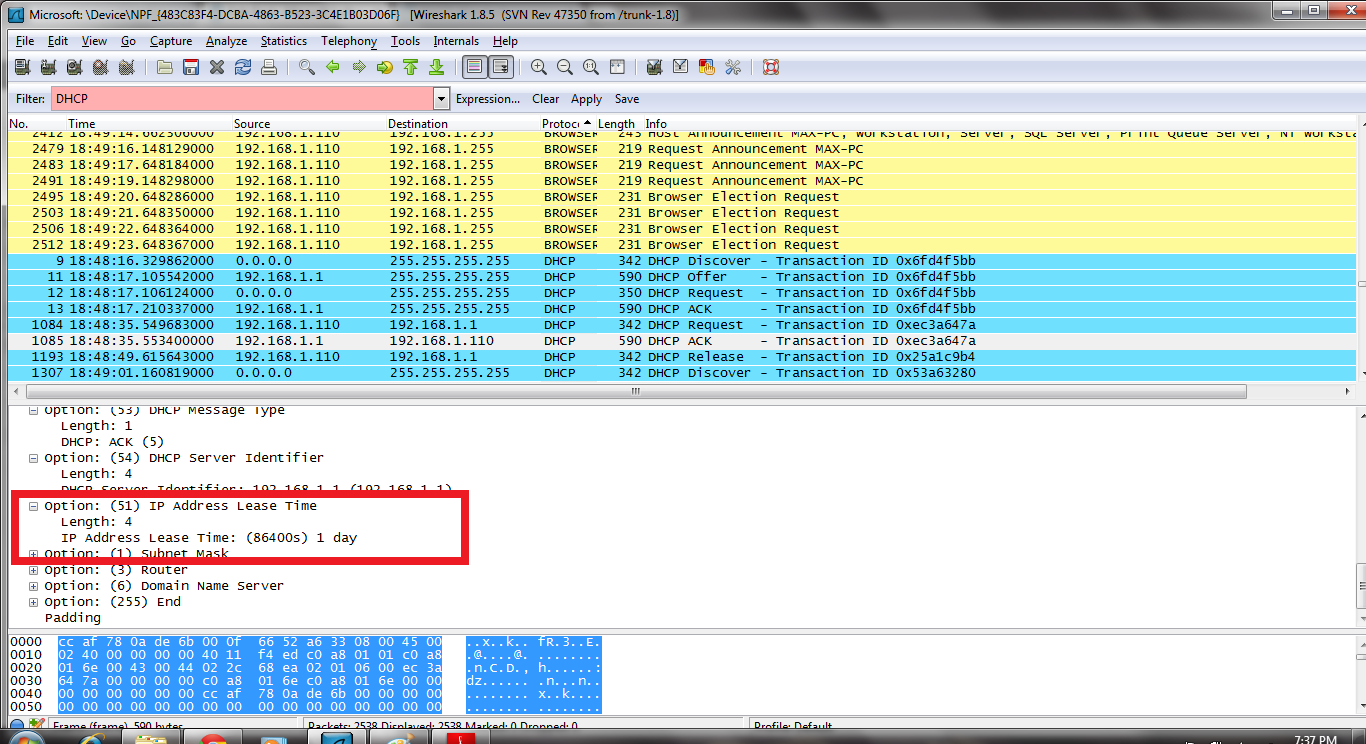
12. Explain the purpose of the lease time. How long is the lease time in your experiment?
- The purpose of lease time is to tell the client how long they can use the specific IP address assigned by the server before they will have to be assigned a new one.
- The lease time in my experiment is 86400 seconds or 1 day
13. What is the purpose of the DHCP release message? Does the DHCP server issue an acknowledgment of receipt of the client’s DHCP request? What would happen if the client’s DHCP release message is lost?
- The purpose of the release message is to release the IP address back to the server.
- There is no verification that the release message has been received by the server.
- If the message is lost, the client releases the IP address, but the server will not reassign that address until the clients lease on the address expires.
14. Clear the bootp filter from your Wireshark window. Were any ARP packets sent or received during the DHCP packet-exchange period? If so, explain the purpose of those ARP packets.
- Yes, they appear to be broadcasts sent out by the network to build up the known IP addresses by the clients network.

Lab Video:
———————————————————————————————————————————————————————-
Steps:
1.Start up Wireshark and begin packet capture (Capture->Start) and then press OK on the Wireshark Packet Capture Options screen
2. If you are using a Windows platform, start up pingplotter and enter the name of a target destination in the “Address to Trace Window.” Enter 3 in the “# of times to Trace” field, so you don’t gather too much data. Select the menu item Edit->Advanced Options->Packet Options and enter a value of 56 in the Packet Size field and then press OK. Then press the Trace button
3. Send a set of datagrams with a longer length, by selecting Edit->Advanced Options->Packet Options and enter a value of 2000 in the Packet Size field and then press OK. Then press the Resume button.
4.Finally, send a set of datagrams with a longer length, by selecting Edit->Advanced Options->Packet Options and enter a value of 3500 in the Packet Size field and then press OK. Then press the Resume button.
5.Stop Wireshark tracing.
———————————————————————————————————————————————————————-
Questions:
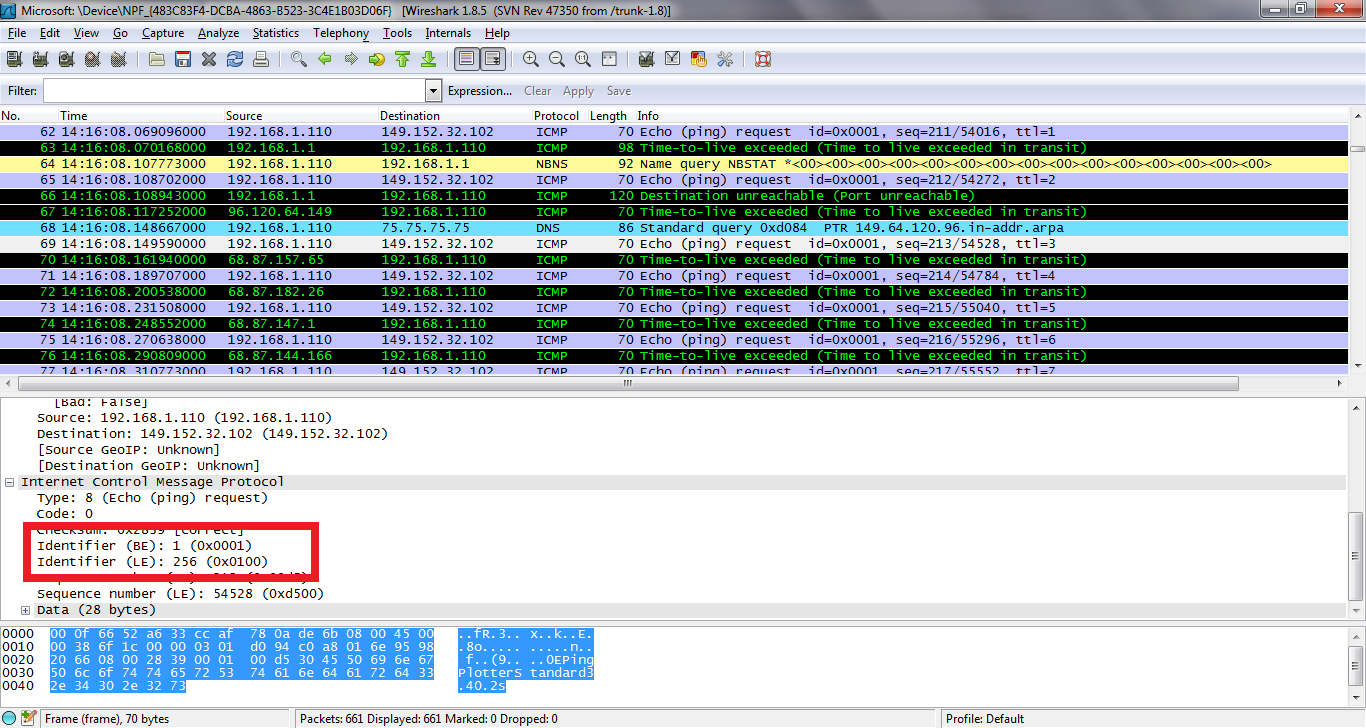
1. What is the IP address of your computer?
- The IP address of my computer is 192.168.1.110
2. Within the IP packet header, what is the value in the upper layer protocol field?
- The value of the upper layer protocol field is ICMP (0X01)
3. How many bytes are in the IP header? How many bytes are in the payload of the IP datagram? Explain how you determined the number of payload bytes.
- There are 20 bytes in the IP header which leaves 36 bytes for the payload of the IP datagram because we were sending a packet of length 56 bytes.

4. Has this IP datagram been fragmented? Explain how you determined whether or not the datagram has been fragmented.
- The fragment offset is set to 0, therefore, the packet has not been fragmented.

5. Which fields in the IP datagram always change from one datagram to the next within this series of ICMP messages sent by your computer?
- The header checksum and the Identification changes from each datagram to the next.
6. Which fields stay constant? Which of the fields must stay constant? Which fields must change? Why?
Fields that stay constant:
- Version(IPv4)
- Length of header
- Source IP(sending from same place)
- Destination IP(contacting same site)
- Upper layer protocol(always using ICMP)
Fields that must stay constant:
- Same as above
The fields that must change are:
- The header checksum (header changes)
- Identification(to verify packets)
7. Describe the pattern you see in the values in the Identification field of the IP datagram
- The pattern in the identification field is that the field increases by one in each strand of echo requests. (see video for proof)
8. What is the value in the Identification field and the TTL field?
- Identification: 28451
- TTL: 10
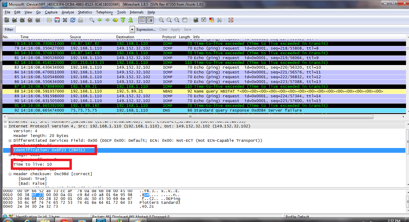
9. Do these values remain unchanged for all of the ICMP TTL-exceeded replies sent to your computer by the nearest (first hop) router? Why?
- The Identification field changes from all of the replies because this field has to have a unique value. If they(2 or more replies) have the same value then the replies must be fragments of a bigger packet.
- The TLL field does not change because the time to live to the first hop router is always the same.
10. Find the first ICMP Echo Request message that was sent by your computer after you changed the Packet Size in pingplotterto be 2000. Has that message been fragmented across more than one IP datagram?
- Yes, that message has been fragmented across more than one IP datagram.

11. Print out the first fragment of the fragmented IP datagram. What information in the IP header indicates that the datagram been fragmented? What information in the IP header indicates whether this is the first fragment versus a latter fragment? How long is this IP datagram?
- The fact that the flag is set for more segments shows that the the datagram has been fragmented (see above).The fragment offset is set to 0 indicating that this is the first fragment rather than a latter fragment where that value is is set to (1480). The datagram has a total length of 1500.

12. Print out the second fragment of the fragmented IP datagram. What information in the IP header indicates that this is not the first datagram fragment? Are the more fragments? How can you tell?
- The second fragment is obvious because it now has a a fragment offset of 1480. There are no more fragments because it no longer has a flag set for more fragments
.
13. What fields change in the IP header between the first and second fragment?
- The fields that change are
- Length
- Flags Set
- Fragment offset
- header checksum
14. How many fragments were created from the original datagram?
- After switching to 3500 bytes, 3 fragements are created.
15. What fields change in the IP header among the fragments?
- The fields that change are the fragment offset (0, 1480, 2960) and checksum. The first 2 packets also have lengths of 1500 and more fragments flags set, while the last fragment is shorter (540) and does not have a flag set.
#include “stdafx.h”
#include “RDT.h”
#include “StudentWork.h”
/********* STUDENTS WRITE THE NEXT SEVEN ROUTINES *********/
//chapter 3.4 pg 221
//global variables
int gBase;
int gNextSeqNum;
const int gN = 5; //this is the N in GoBackN in this case GoBack5
const int gSimMaxPkts = 100;//Maximum number of simulated packets
struct pkt gSendPkt[gSimMaxPkts];//Array for sending in order
const int gPayLoadSize = 20;//Maximum amout of information in checksum
const float gTimeOutSeconds = 20.0; //global for timeout in seconds
/* the following routine will be called once (only) before any other */
/* entity A routines are called. You can use it to do any initialization
Initialization routine*/
void A_init()
{
// This is the init routine for GoBackN pg 221 in text…
//Initialize global variables
gBase = 1;
gNextSeqNum = 1;
}
/* called from layer 5, passed the data to be sent to other side */
void A_output(struct msg message)
{
// A_output is really RDT send on pg 221
/*
p_code from eFSM on page 221 of text
if(nextSeqNum <(base+N){
…..
}
*/
if(gNextSeqNum < gBase+gN)
{
{//This is make packet on page 221 of the text
int checkSum = 0;//Inital Checksum =0
for (int i=0; i<gPayLoadSize; i++)//Send in incriments of 1 until payload is full
{
gSendPkt[gNextSeqNum].payload[i] = message.data[i];//sent packet with the first payload and first message segment ++
checkSum += message.data[i];//the checksum should be for the message data value
}
gSendPkt[gNextSeqNum].checksum = checkSum;//set to next checksum number for next packet
gSendPkt[gNextSeqNum].seqnum = gNextSeqNum;//get the next sequence number for the packet
}
//udt_send
tolayer3(A,gSendPkt[gNextSeqNum]);//send packet A to transport layer
if(gBase == gNextSeqNum)//Start the timeout timer after packet sent
//start time goes here
starttimer(A, gTimeOutSeconds);
gNextSeqNum++;
}
//else refuse on pg 221 is not implemented.
}
/* called from layer 3, when a packet arrives for layer 4 */
void A_input(struct pkt packet)
{
//check to see if pkt is not corrupt
int checkSum = 0;//set checksum to 0
for (int i=0; i<gPayLoadSize; i++)//add 1 to payload for each packet as it is sent
{
checkSum += packet.payload[i];//checksum should = the payload
}
if (checkSum != packet.checksum)//if the checksum is not equal to the packet checksum
{
printf(“\n Bad Checksum on Ack … Skipping\n”);//Drop the ack message and resend
return;
}
//if it is good, update base… pg 221
gBase = packet.acknum+1;
if(gBase ==gNextSeqNum)
stoptimer(A);//stop timer
else
starttimer(A, gTimeOutSeconds);//Start timer
}
/* called when A’s timer goes off */
void A_timerinterrupt()
{
//timeOut event on pg 221
starttimer(A, gTimeOutSeconds);
for (int i=gBase; i<gNextSeqNum; i++)//udt send
tolayer3(A,gSendPkt[i]);// resend packet
}
///////////////////////////////////////////////////////////////////////////////////////////////////////////////////
//////////////////////////////////////////////////////////////////////////////////////////////////////////////////
//global variables that deal with part B
int gExpectedSequenceNumber;
struct pkt gAckPkt;
void B_output(struct msg message) /* need be completed only for extra credit */
{
}
/* Note that with simplex transfer from a-to-B, there is no B_output() */
/* called from layer 3, when a packet arrives for layer 4 at B*/
void B_input(struct pkt packet)
{
// corrupt or not expected got to do default…..
// check to see if packet not corrupt
int checkSum =0;
for(int i=0;i<gPayLoadSize;i++)
{
checkSum += packet.payload[i];
}
if (checkSum != packet.checksum) //If it is a bad checksum
{
tolayer3(B,gAckPkt);
printf(“\n Bad Checksum on Recrvr Packet, send Dup ACK…. skipping\n”);//State bad packet and send a duplicate ack asking for retransmit
return;
}
if (packet.seqnum != gExpectedSequenceNumber)//If the packet number is out of order
{
tolayer3(B,gAckPkt);
printf(“\n Not Expected send Dup Ack…. skipping\n”);//SState bad packet and send a duplicate ack asking for retransmit
return;
}
// not corrupt and expected
tolayer5(B,packet.payload);
gAckPkt.acknum =gExpectedSequenceNumber;//the ack message should include the corresponding sequence number
gAckPkt.payload[0] = ‘A’;gAckPkt.payload[1] = ‘C’;gAckPkt.payload[2] = ‘K’;//include in the ack message
gAckPkt.checksum = ‘A’+’C’+’K’;//include in the checksum
tolayer3(B,gAckPkt);
gExpectedSequenceNumber++;//up the expected sequence number for the next packet
}
/* called when B’s timer goes off */
void B_timerinterrupt()
{
}
/* the following rouytine will be called once (only) before any other */
/* entity B routines are called. You can use it to do any initialization */
void B_init()
{
gAckPkt.acknum = 0;//Ack Messages will a start at 0
gAckPkt.payload[0] = ‘A’; gAckPkt.payload[1] = ‘C’; gAckPkt.payload[2] = ‘K’;//What the AckPkts will contain
gAckPkt.checksum = ‘A’ + ‘C’ +’K’;//What checksum will include
int gExpectedSequenceNumber = 1;//Sequence of messages to start at 1
}
———————————————————————————————————————————————————————-
Lab Video:
Screen Shots:
Base Case: No Loss, No Corruption, 1 Packet Sent, Trace 5

8 Packets Sent, No Loss, No Corruption, Trace 3

8 Packets Sent, 50% Loss, No Corruption, Trace 3

8 Packets Sent, No Loss, 50% Corruption, Trace 3

8 packets sent, 50% Loss, 50% Corruption
 [
[
Question #5: Suppose that the UDP receiver computes the Internet checksum for the received UDP segment and finds that it matches the value carried in the checksum field.Can the receiver be absolutely certain that no bit errors have occurred? Explain
No, the receiver can no be absolutely certain that no errors have occurred. As discussed in class, a checksum will always detect the error if only one occurs, however, multiple errors are tough for a checksum to detect due to its lack of advanced checking capabilities. For example if a packet sends [3|5], the checksum a combination of the two would be 8, therefore the entire sent packet is [8|3|5]. However, because checksum is very limited, as long as the checksum value (in this case 8) is correct, then it will assume the packet is correct. The binary codes for 3 and 5 are 011 and 101 respectively, if only one bit is changed in each of these codes, the binary codes can then become 111 and 001 or 7 and 1. If this were to happen, 7+1 still equals 8, therefore the checksum value would be correct and the computer would assume that no bit errors have occurred although as you can see the packet has been changed greatly from [3|5] to [7|1].
Question #10: Consider a channel that can lose packets but has a maximum delay that is known. Modify protocol rdt 2.1 to include sender timeout and retransmit. Informally argue why your protocol can communicate correctly over this channel.
![IMG_0486[1]](https://maxwellsullivan.files.wordpress.com/2013/03/img_04861.jpg)
In order to modify the above protocol to include a sender timeout and retransmit, we must add a timer. An example that seems to solve this issue is the RDT 3.0 Sender. It is much the protocol for RDT 2.1, but includes a timeout. This protocol would communicate correctly because it doesn’t require anything but a resend without the acknowledgement. It doesn’t require that a message be received, just that if a message is not received the message must be resent.
![IMG_0487[1]](https://maxwellsullivan.files.wordpress.com/2013/03/img_04871.jpg)
Question #15: Consider the cross-country example shown in Figure 3.17. How big would the window size have to be for the channel utilization to be greater than 98 percent? Suppose that the size of a packet is 1,500 bytes, including both header fields and data.
![IMG_0488[1]](https://maxwellsullivan.files.wordpress.com/2013/03/img_04881.jpg)
If we assume that the transmission rate is the same as the example (or 1 Gbps), then it takes 12 Microseconds (or .012 ms) in order to send the packet.

If we also assume that the RTT is 30 milliseconds as it is in figure 3.17, then the utilization of the link can be shown as U = (.012*n)/30.012, where n is the number of packets necessary to be in the window to equal the desired utilization. Therefore if we set this equation equal to the desired utilization or 0.98, the equation is as follows U=.98=(.012*n)/30.012 and solve for n, we find that 2451 packets must be being sent in order for 98% utilization to occur.

Question #22: Consider the GBN protocol with a sender window size of 4 and a sequence number range of 1,024. Suppose that at time t , the next in-order packet that the receiver is expecting has a sequence number of k. Assume that the medium does not reorder messages. Answer the following questions:
a.What are the possible sets of sequence numbers inside the sender’s window at time t ? Justify your answer.
- We are told that we have a window size of N=4. Assuming that the receiver has received up to packet K-1, because it is now expecting k, and has Acked all off these previous packets. Assuming now that the sender has received all of these acked messages, then the senders window can be represented as [K, K+N-1]. If none of the Acks have been received by the sender, then the window can be represented as [k-N, K-1]. Based on these arguments and the senders window being of size 4 begins somewhere in the range of [k-4,k].
b.What are all possible values of the ACK field in all possible messages currently propagating back to the sender at time t ? Justify your answer.
- If the receiver is waiting for packet with sequence number K, then it has received the packet before that (k-1) and all packets leading up to that point as well (N-1). Because the sender has already sent packet [K-N, K-1] then the sender must have already received the ack for K-N-1. Once the receiver has sent the ack for K-N-1, it will not resend this ack, assuming no that the ack message is not lost resulting in retransmission, therefore it will not send an Ack lower than K-N-1, meaning the current value of ack messages propagating across the network is K-5, K-1.
Question #26: Consider transferring an enormous file of L bytes from Host A to Host B.Assume an MSS of 536 bytes.
a.What is the maximum value of L such that TCP sequence numbers are not exhausted? Recall that the TCP sequence number field has 4 bytes.
- For this, we must convert the 4 bytes of the number field to 32 bits. Therefore, L can be denoted as 2^32 meaning that L is equal to 4,294,967,296 bits.
b.For the L you obtain in (a), find how long it takes to transmit the file. Assume that a total of 66 bytes of transport, network, and data-link header are added to each segment before the resulting packet is sent out over a 155 Mbps link. Ignore flow control and congestion control so A can pump out the segments back to back and continuously
- Each packet is total is 536 bytes, we are told that 66 bytes are needed for transport, network, and data link headers. Therefore, 470 bytes of each packet contain data. We can then divide the total number of bits that need to be sent from part A (4,294,967,296) by the amount of data we can send in each packet(470*8) to find the total number of packets we need to send. 1,142,279 packets need to be sent in order to send all the data. Because each packet holds 536 bytes, we will be sending a total of 4,898,090,363 bits at a rate of 155 Mbps, for a total of 31.6 seconds to transmit the entire file.

Question #28: Host A and B are directly connected with a 100 Mbps link. There is one TCP connection between the two hosts, and Host A is sending to Host B an enormous file over this connection. Host A can send its application data into its TCP socket at a rate as high as 120 Mbps but Host B can read out of its TCP receive buffer at a maximum rate of 50 Mbps. Describe the effect of TCP flow control.
- Based on the information above, we know that host A is sending data faster (120 Mbps) than host B can receive it (50 Mbps). The rate of sending versus the ability to receive is over two time as much, this means that the buffer will fill relatively quickly. Once this buffer fills up, Host B will signal host A to stop sending until it is ready again by setting the RCVWindow down to 0. Host A will then send at the rate that Host B specifies in the RCVWindow messages, this is the benefit of flow control as offered by TCP.
Question #29: SYN cookies were discussed in Section 3.5.6.
a.Why is it necessary for the server to use a special initial sequence number in the SYN ACK?
- According to wikipedia, a special initial sequence number is necessary in the SYN ACK in order for TCP to be able to reassemble the data steam in the appropriate order.
b.Suppose an attacker knows that a target host uses SYN cookies. Can the attacker create half-open or fully open connections by simply sending an ACK packet to the target? Why or why not?
- The attacker can no longer create a half-open circuit by sending packets to a server. Unlike before the use of SYN cookies when a server could receive a SYN message and then sit in limbo waiting for an ACK in response to its SYNACK to the message, since the introduction of cookies this is much more difficult, Clients must now return ACK segments that the server will verify belong to an earlier SYN, creating a fully open connection. If no ACK is returned, the the server doesn’t allocate any resources to the original SYN. In conclusion, a server must receive a SYN message, reply with a SYN ACK, then receive an ACK for resources to be consumed by a user, therefore, no an attacker could not bring down a host simply by sending ACK packets.
- I referenced “Computer Networking: A Top Down Approach” Section 3.5 Focus on Security pg 283 (Int’l Ed.) for this question on 3/12/2013
c.Suppose an attacker collects a large amount of initial sequence numbers sent by the server. Can the attacker cause the server to create many fully open connections by sending ACKs with those initial sequence numbers? Why?
- The attacker could not attack this way either, the server checks Ack messages not only by using the initial sequence number, but also checks for a corresponding SYN message from the same sender by using a hash function to check for the same source and destination IP addresses and port numbers from the original SYN message.
- I referenced “Computer Networking: A Top Down Approach” Section 3.5 Focus on Security pg 283 (Int’l Ed.) for this question on 3/12/2013
Question #32: Consider the TCP procedure for estimating RTT. Suppose that (alpha)= 0.1. Let SampleRTT1 be the most recent sample RTT, let SampleRTT2 be the next most recent sample RTT, and so on.
a.For a given TCP connection, suppose four acknowledgments have been returned with corresponding sample RTTs: Sample RTT4, Sample RTT3, Sample RTT2, and Sample RTT1. Express EstimatedRTT in terms of the four sample RTTs.
- Estimated RTT =( (1-alpha)ERTT1 +(alpha)SRTT1)+ ( (1-alpha)(alpha)ERTT2 +(alpha)SRTT2)+ ( (1-alpha^2)(alpha)ERTT3 +(alpha)SRTT3)+( (1-alpha^3)(alpha)ERTT4 +(alpha)SRTT4)
b.Generalize your formula for n sample RTTs.
- ERTT =( (1-alpha)^(n-1))(alpha)ERTT + (alpha)SRTTn
c. For the formula in part (b) let n approach infinity. Comment on why this averaging procedure is called an exponential moving average.
- This procedure is called an exponential moving average because as each RTT is added, the weight of the earlier RTTs in terms of the overall formula decays exponentially.
Question #55: In this problem we investigate whether either UDP or TCP provides a degree of end-point authentication.
a.Consider a server that receives a request within a UDP packet and responds to that request within a UDP packet (for example, as done by a DNS server). If a client with IP address X spoofs its address with address Y, where will the server send its response?
- The server would send to the client with address X because it is unconcerned with the IP address, it simply sends back to the corresponding port number.
b.Suppose a server receives a SYN with IP source address Y, and after responding with a SYN ACK, receives an ACK with IP source address Y with the correct acknowledgment number. Assuming the server chooses a random initial sequence number and there is no “man-in-the-middle,” can the server be certain that the client is indeed at Y(and not at some other address X that is spoofing Y)?
- The server can be certain that the client is indeed at Y because not only does the server check to ensure that the ACK includes the correct acknowledgement number, it also checks the senders IP and port number against previously received SYN messages to ensure that the sender of the ACK is the one who sent the initial SYN message if the server uses SYN Cookies.
Lab Video:
STEPS:
Start capturing packets in Wireshark and then do something that will cause your host to send and receive several UDP packets. It’s also likely that just by doing nothing (except capturing packets via Wireshark) that some UDP packets sent by others will appear in your trace. In particular, the Simple Network Management Protocol (SNMP – chapter 9 in the text) sends SNMP messages inside of UDP, so it’s likely that you’ll find some SNMP messages (and therefore UDP packets) in your trace.
QUESTIONS:
1. Select one UDP packet from your trace. From this packet, determine how many fields there are in the UDP header. (You shouldn’t look in the textbook! Answer these questions directly from what you observe in the packet trace.) Name these fields.
- The header only contains 4 fields: the source port, destination port, length, and checksum.

2. By consulting the displayed information in Wireshark’s packet content field for this packet, determine the length (in bytes) of each of the UDP header fields.
- Each of the UDP header fields is 2 bytes long
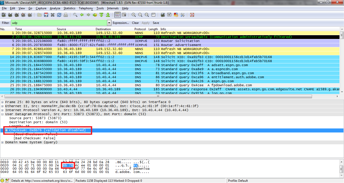
3. The value in the Length field is the length of what? (You can consult the text for this answer). Verify your claim with your captured UDP packet.
- The value in the length field, in the example below it is 46, is the sum of the 8 header bytes and the remaining data bytes encapsulated in the packet.
4. What is the maximum number of bytes that can be included in a UDP payload? (Hint: the answer to this question can be determined by your answer to 2. above)
- The maximum number of bytes that can be in the payload is 2^16- the bytes already being used by the header field (8). Therefore the maximum payload is 65535-8= 65527 bytes.
5. What is the largest possible source port number? (Hint: see the hint in 4.)
- The largest possible source port number is 2^16 or 65535.
6. What is the protocol number for UDP? Give your answer in both hexadecimal and decimal notation. To answer this question, you’ll need to look into the Protocol field of the IP datagram containing this UDP segment (see Figure 4.13 in the text, and the discussion of IP header fields).
- The protocol number for UDP is 17 in decimal notation which in hexadecimal notation is 0x11.

7. Examine a pair of UDP packets in which your host sends the first UDP packet and the second UDP packet is a reply to this first UDP packet. (Hint: for a second packet to be sent in response to a first packet, the sender of the first packet should be the destination of the second packet). Describe the relationship between the port numbers in the two packets
UDP Sent by my host

UDP Reply to Host

- The relationship between port numbers is that the source port on the send message is the destination port of the receive message. The destination port for the send message is also the source port for the receive message.
PART 1: Capturing a bulk TCP transfer from your computer to a remote server
Lab Video:
STEPS:
1. Start up your web browser. Go the http://gaia.cs.umass.edu/wiresharklabs/alice.txt and retrieve an ASCII copy of Alice in Wonderland. Store this file somewhere on your computer.
2. Next go to http://gaia.cs.umass.edu/wireshark-labs/TCP-wireshark-file1.html.
3. Use the Browse button in this form to enter the name of the file (full path name) on your computer containing Alice in Wonderland (or do so manually). Don’t yet press the “Upload alice.txt file” button.
4. Now start up Wireshark and begin packet capture (Capture->Start) and then press OK on the Wireshark Packet Capture Options screen (we’ll not need to select any options here).
5. Returning to your browser, press the “Upload alice.txt file” button to upload the file to the gaia.cs.umass.edu server. Once the file has been uploaded, a short congratulations message will be displayed in your browser window.
6. Stop Wireshark packet capture. Your Wireshark window should look similar to the window shown below.
———————————————————————————————————————————————————————-
PART 2: A first Look At the Captured Trace
Use the online capture (shown below) to answer the following:
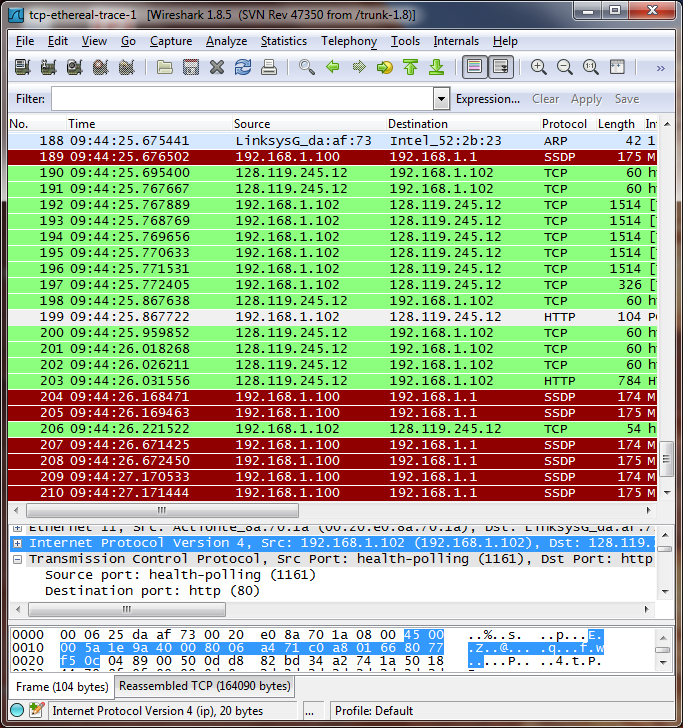
1. What is the IP address and TCP port number used by the client computer (source) that is transferring the file to gaia.cs.umass.edu? To answer this question, it’s probably easiest to select an HTTP message and explore the details of the TCP packet used to carry this HTTP message, using the “details of the selected packet header window” (refer to Figure 2 in the “Getting Started with Wireshark” Lab if you’re uncertain about the Wireshark windows.
- The source IP address was 192.168.102 using source port 1161.
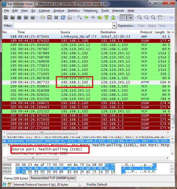
2. What is the IP address of gaia.cs.umass.edu? On what port number is it sending and receiving TCP segments for this connection?
- The destination IP address is 128.119.245.12 receiving on port 80

Use your own Capture to answer the following:
3. What is the IP address and TCP port number used by your client computer (source) to transfer the file to gaia.cs.umass.edu?
- My IP address source is 10.36.40.136 sending on port 54360.

———————————————————————————————————————————————————————-
PART 3: TCP Basics
4. What is the sequence number of the TCP SYN segment that is used to initiate the TCP connection between the client computer and gaia.cs.umass.edu? What is it in the segment that identifies the segment as a SYN segment?
- The sequence number of the segment used to initiate the TCP connection is 0. We can see that the message contains a SYN flag indicating that it is a SYN segment.

5. What is the sequence number of the SYNACK segment sent by gaia.cs.umass.edu to the client computer in reply to the SYN? What is the value of the Acknowledgement field in the SYNACK segment? How did gaia.cs.umass.edu determine that value? What is it in the segment that identifies the segment as a SYNACK segment?
- The sequence number of the SYNACK segment is 0.
- The value of the acknowledgement field is 1. This value is determined by the initial sequence number +1.
- The message carries flags that show it to be a SYN ACK message.

6. What is the sequence number of the TCP segment containing the HTTP POST command? Note that in order to find the POST command, you’ll need to dig into the packet content field at the bottom of the Wireshark window, looking for a segment with a “POST” within its DATA field.
- The sequence number of the TCP segment containing the HTTP Post Command is 149571.

7. Consider the TCP segment containing the HTTP POST as the first segment in the TCP connection. What are the sequence numbers of the first six segments in the TCP connection (including the segment containing the HTTP POST)? At what time was each segment sent? When was the ACK for each segment received? Given the difference between when each TCP segment was sent, and when its acknowledgement was received, what is the RTT value for each of the six segments? What is the EstimatedRTT value (see Section 3.5.3, page 239 in text) after the receipt of each ACK? Assume that the value of the EstimatedRTT is equal to the measured RTT for the first segment, and then is computed using the EstimatedRTT equation on page 239 for all subsequent segments.

8. What is the length of each of the first six TCP segments?
- The length of each of the first TCP segment is 708. The following segments are all 1514.
9. What is the minimum amount of available buffer space advertised at the received for the entire trace? Does the lack of receiver buffer space ever throttle the sender?
- The minimum amount of available buffer space is listed as 65535. The sender is never throttled because we never reach full capacity of the window.
10. Are there any retransmitted segments in the trace file? What did you check for (in the trace) in order to answer this question?
- No, no segments were ever retransmitted. This is shown by the fact that an old Acknowledgement number was never resent in order to re-request former packets.
11. How much data does the receiver typically acknowledge in an ACK? Can you identify cases where the receiver is ACKing every other received segment (see Table 3.2 on page 247 in the text).
- The receiver is typically acking 432 bits. There are cases where the receiver acks every other segment. This is shown when more than one ack occurs in a row.
12. What is the throughput (bytes transferred per unit time) for the TCP connection? Explain how you calculated this value.
- The throughput can be calculated by using the value of the last ack(149,629)- the first sequence number(1) divided by the time since first frame (1.6) = 93517.6 bps.
———————————————————————————————————————————————————————-
PART 4: TCP Congestion Control In Action
STEPS:
1. Select a TCP segment in the Wireshark’s “listing of captured-packets” window. Then select the menu : Statistics->TCP Stream Graph-> Time-SequenceGraph(Stevens).
QUESTIONS:
Answer Question 13 Using the provided Capture
13. Use the Time-Sequence-Graph(Stevens) plotting tool to view the sequence number versus time plot of segments being sent from the client to the gaia.cs.umass.edu server. Can you identify where TCP’s slowstart phase begins and ends, and where congestion avoidance takes over? Comment on ways in which the measured data differs from the idealized behavior of TCP that we’ve studied in the text.
The TCP slowstart phase begins at just above seq number 5000, and ends just before sequence number 10000. Congestion avoidance takes over at 10000.

Part 1: NSLookup
1. Run nslookup to obtain the IP address of a Web server in Asia. What is the IP address of that server?
- For this question, I queried the webpage for the Asian Institute of Technology in Thialand. The IP address of that server was 203.159.12.3.

2. Run nslookup to determine the authoritative DNS servers for a university in Europe.
- For this question, I used the webpage for Cambridge University in England. This webpage is http://www.cam.ac.uk. The authoritative DNS server is authdns0.csx.cam.ac.uk.

3. Run nslookup so that one of the DNS servers obtained in Question 2 is queried for the mail servers for Yahoo! mail. What is its IP address?
- The IP addreess for the DNS server if queried for the Yahoo! mail server is 209.191.122.42
 ———————————————————————————————————————————————————————-
Part 2: IPconfig
There are no questions for part two of this lab. All it requires is that we run IPconfig /all on our current machine. This will display my machines current TCP/IP information, including my IP address, DNS server address and other additional information.

It then asks that we display our recent cached memory by using the command ipconfig /displaydns

Finally, we are told to clear the above cache by entering IPconfig /flushdns

———————————————————————————————————————————————————————-
Part 3: Tracing DNS with Wireshark
Lab Video: for Part 1
STEPS: Part 1: IPconfig
Step 1: Use ipconfig to empty the DNS cache in your host.
Step 2: Open your browser and empty your browser cache. (With Internet Explorer, go to Tools menu and select Internet Options; then in the General tab select Delete Files.)
Step 3: Open Wireshark and enter “ip.addr == your_IP_address” into the filter, where you obtain your_IP_address with ipconfig. This filter removes all packets that neither originate nor are destined to your host.
Step 4: Start packet capture in Wireshark.
Step 5: With your browser, visit the Web page: http://www.ietf.org
Step 6: Stop packet capture.

QUESTIONS:
4. Locate the DNS query and response messages. Are then sent over UDP or TCP?
- The DNS query and response messages are sent over UDP.

5. What is the destination port for the DNS query message? What is the source port of DNS response message?
- The destination port is 53
- The source port is 50133
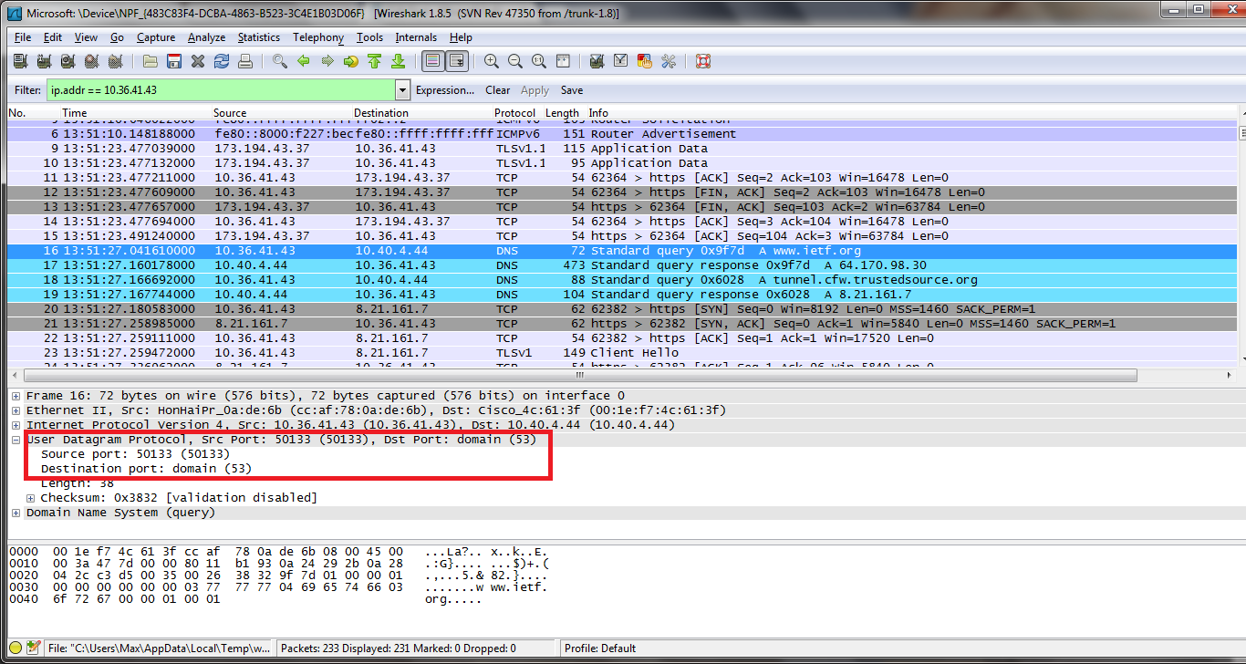
6. To what IP address is the DNS query message sent? Use ipconfig to determine the IP address of your local DNS server. Are these two IP addresses the same?
- The DNS query was sent to IP address 10.40.4.44. Yes it is the same IP address as that of my local DNS server.

7. Examine the DNS query message. What “Type” of DNS query is it? Does the query message contain any “answers”?
- The query message was a type “A” query, but the message did not contain any “answers.”

8. Examine the DNS response message. How many “answers” are provided? What do each of these answers contain?
- The response message contained one answer to the query which was the sites address [64.170.98.30]. Although it also provided 6 authoritative nameservers, and 11 other responses containing additional information.

9. Consider the subsequent TCP SYN packet sent by your host. Does the destination IP address of the SYN packet correspond to any of the IP addresses provided in the DNS response message?
- The destination of the SYN packet is 64.170.98.30, the same address that was provided in the DNS response message as the type “A” address of the webpage.
10. This web page contains images. Before retrieving each image, does your host issue new DNS queries?
- Yes, my host did issue new DNS queries before the images were retrieved. For example, one such query was for an image from open-stand.org. The image corresponding to the page was not returned until this query was made.

———————————————————————————————————————————————————————-
Lab Video, Part 2:
STEPS: Part 2: NSLookup
Step 1: Start packet capture.
Step 2: Do an nslookup on http://www.mit.edu
Step 3: Stop packet capture.

QUESTIONS
11. What is the destination port for the DNS query message? What is the source port of DNS response message?
- Destination Port: 53
- Source Port: 53098

12. To what IP address is the DNS query message sent? Is this the IP address of your default local DNS server?
- The DNS query message is sent to IP address 10.40.4.44, the same address as my default local DNS server.
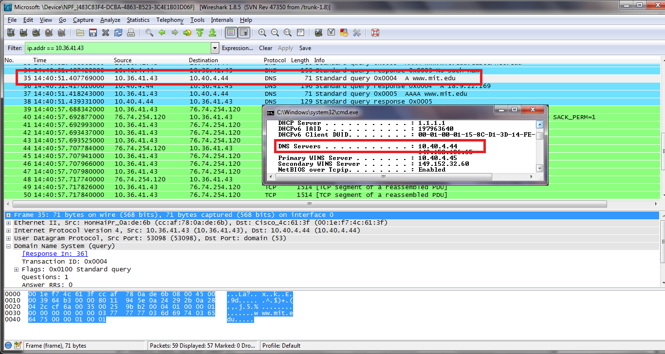
13. Examine the DNS query message. What “Type” of DNS query is it? Does the query message contain any “answers”?
- The DNS query message is a type “A” query, containing only one question and not containing any answers.
14. Examine the DNS response message. How many “answers” are provided? What do each of these answers contain?
- The response message contains one answer to the aformentioned query which is the type “A” address of http://www.mit.edu or 18.9.22.169. It also contained information on 3 authoritative nameservers and 3 additional records.
15. Provide a screenshot.
- See bottom of steps
———————————————————————————————————————————————————————-
Lab Video Part 2.1:
STEPS:
Step 1: repeat the previous experiment
Step 2: but instead issue the command: nslookup –type=NS mit.edu

QUESTIONS:
16. To what IP address is the DNS query message sent? Is this the IP address of you default local DNS server?
- The query is sent to 10.40.4.44, the same IP address as that of my default local DNS server.
17. Examine the DNS query message. What “Type” of DNS query is it? Does the query message contain any “answers”
- The DNS query is a type “NS” message including one question. The query message did not contain any answers.

18. Examine the DNS response message. What MIT nameservers does the response message provide? Does this response message also provide the IP addresses of the MIT namesevers?
- The response message provides 3 MIT nameservers: w20ns.mit.edu[18.70.0.160], strawb.mit.edu[18.71.0.150], and bitsy.mit.edu[18.72.0.3]. The IP addresses for the nameservers was included under the additional records category sent back as part of the response message.

19. Provide a screenshot.
- See image under lab steps for Part 2.1
———————————————————————————————————————————————————————-
Lab 3, Part 2.2 Video:
STEPS:
Step 1: Now repeat the previous experiment
Step 2: but instead issue the command: nslookup http://www.aiit.or.kr bitsy.mit.edu

QUESTIONS:
20. To what IP address is the DNS query message sent? Is this the IP address of your default local DNS server? If not, what does the IP address correspond to?
- This DNS query message is sent to 149.152.136.65 which is the IP address of the MIT DNS response sender.

21. Examine the DNS query message. What “Type” of DNS query is it? Does the query message contain any “answers”?
- This DNS query is a type “A” query. The message does not contain any answers.

22. Examine the DNS response message. How many “answers” are provided? What does each of these answers contain?
- It only provided one “answer” containing the servers IP address, however, the server also returned a flag that stated that it could complete a recursive query.

23. Provide a screenshot.
- Please see picture under steps
Lab Video:
———————————————————————————————————————————————————————-
STEPS:
Step 1:Make sure your browser’s cache is cleared, as discussed above, and close down your browser. Then, start up your browser
Step 2: Start up the Wireshark packet sniffer
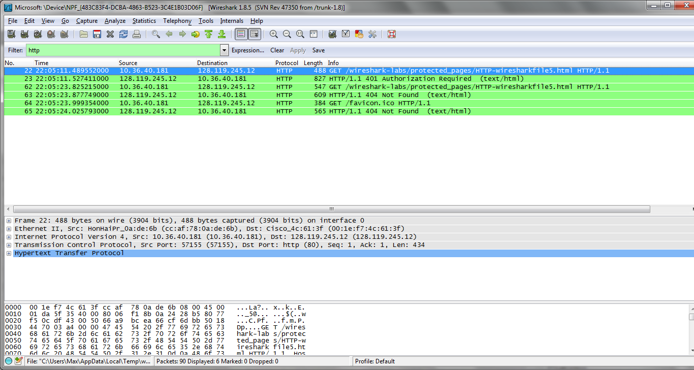
Step 3: Enter the following URL into your browser http://gaia.cs.umass.edu/wireshark-labs/protected_pages/HTTP-wiresharkfile5.html Type the requested user name and password into the pop up box.
Step 4:Stop Wireshark packet capture, and enter “http” in the display-filter-specification window, so that only captured HTTP messages will be displayed later in the packet-listing window.
———————————————————————————————————————————————————————
QUESTIONS:
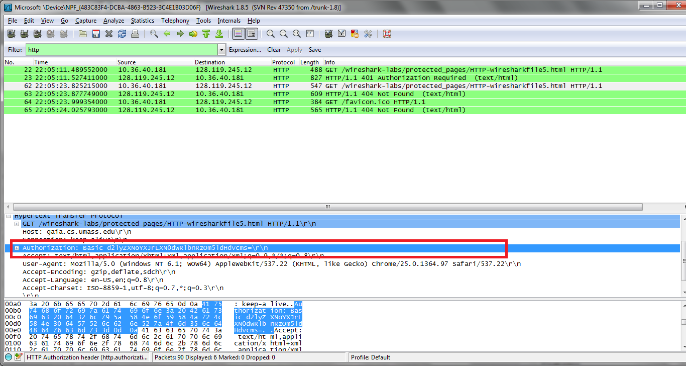
18. What is the server’s response (status code and phrase) in response to the initial HTTP GET message from your browser?
- The servers intial response was “401 Authentication Required”
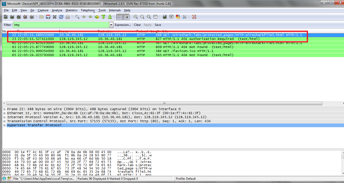
19. When your browser’s sends the HTTP GET message for the second time, what new field is included in the HTTP GET message?
- The new field that is now included is the authorization field. This is included because we sent the server a username and password along with our request stating that we were authorized to receive the page.